Fast Powder
Fast Powder calibration is the quickest way to calibrate your instrument against a known powder standard. It works with a single powder overlay and can refine both instrument parameters and the material's lattice parameters.
The key requirement is that the simulated powder lines must already be relatively close to the observed Debye-Scherrer rings in the data, since the fast powder calibration workflow always performs automatic point-picking. If they are far off, you may need to manually adjust detector positions using the slider view first, or use Composite calibration (which allows manual hand-picking), or Structureless calibration instead.
Starting the Workflow
To begin, ensure that a powder overlay corresponding to the correct material is visible and roughly aligned with the data.
Then navigate to Run -> Calibration -> Fast Powder from the menu bar.
Auto-Picking
Fast Powder calibration uses an automatic peak-picking algorithm to locate the observed powder line positions. The auto-picker works by projecting image data into a polar format (where Debye-Scherrer rings become horizontal straight lines) and then finding peak intensity positions within a user-specified 2θ range. Different types of peak fitting methods are also available.
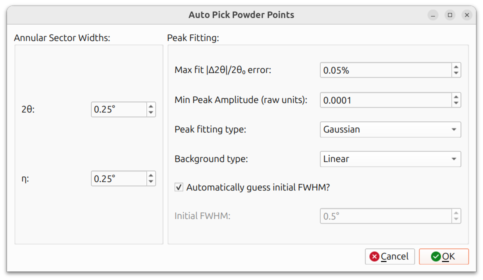
The dialog is divided into two sections:
Annular Sector Widths:
- 2θ: The range in 2θ around each simulated line to search for peaks. A larger value is more forgiving of misalignment but may pick up spurious peaks.
- η: The angular width in η for each pick. A narrower width produces more picks along the ring but may also produce more invalid picks.
Peak Fitting:
- Max Fit |Δ2θ|/2θ₀ error: Picks with a fit error above this threshold are discarded. Lower values are more strict about peak quality.
- Min Peak Amplitude (raw units): Picks with a peak amplitude below this threshold are discarded. This filters out picks on weak or noisy signal.
- Peak fitting type: The function used to fit each peak (e.g., Gaussian, Lorentzian). This affects how precisely the peak center is determined.
- Background type: How the local background is estimated and subtracted before fitting (e.g., linear, constant).
- Automatically guess initial FWHM?: When checked, the initial FWHM is estimated automatically and the Initial FWHM field is disabled. When unchecked, you can specify the initial guess manually.
- Initial FWHM: The initial guess for the full width at half maximum of the peak. Only active when "Automatically guess initial FWHM?" is unchecked. Should be set approximately to the width of the peaks in your data.
Pick Preview
After auto-picking completes, the picks are displayed on the main canvas. You can view them in any of the available view modes, including raw, Cartesian, polar, and stereographic.
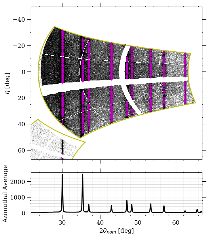
The above image shows a single detector zoomed in on the polar view, where the picks are displayed as purple plus symbols. The polar view is particularly useful here because the powder lines appear as horizontal straight lines, making it easy to see whether the picks are landing on the actual data.
Adjusting Pick Quality
Not all automatically picked points will be valid. Some may land on noise, detector artifacts, or overlapping lines. The Max Fit error and Min Peak Amplitude settings in the auto-pick dialog (described above) help filter these out.
You can also adjust the η width to control the density of picks along each ring. A narrower η width produces more picks, giving the optimizer more data to work with, but it also increases the chance of invalid picks. Finding the right balance depends on your data quality.
If the picks need adjustment, you can re-run the auto-picker with
different settings by navigating to Run -> Calibration -> Fast Powder
again.
Refinement
The calibration dialog presents a tree view of all refinable parameters, including instrument parameters (detector tilts, translations, beam energy, etc.) and material lattice parameters.
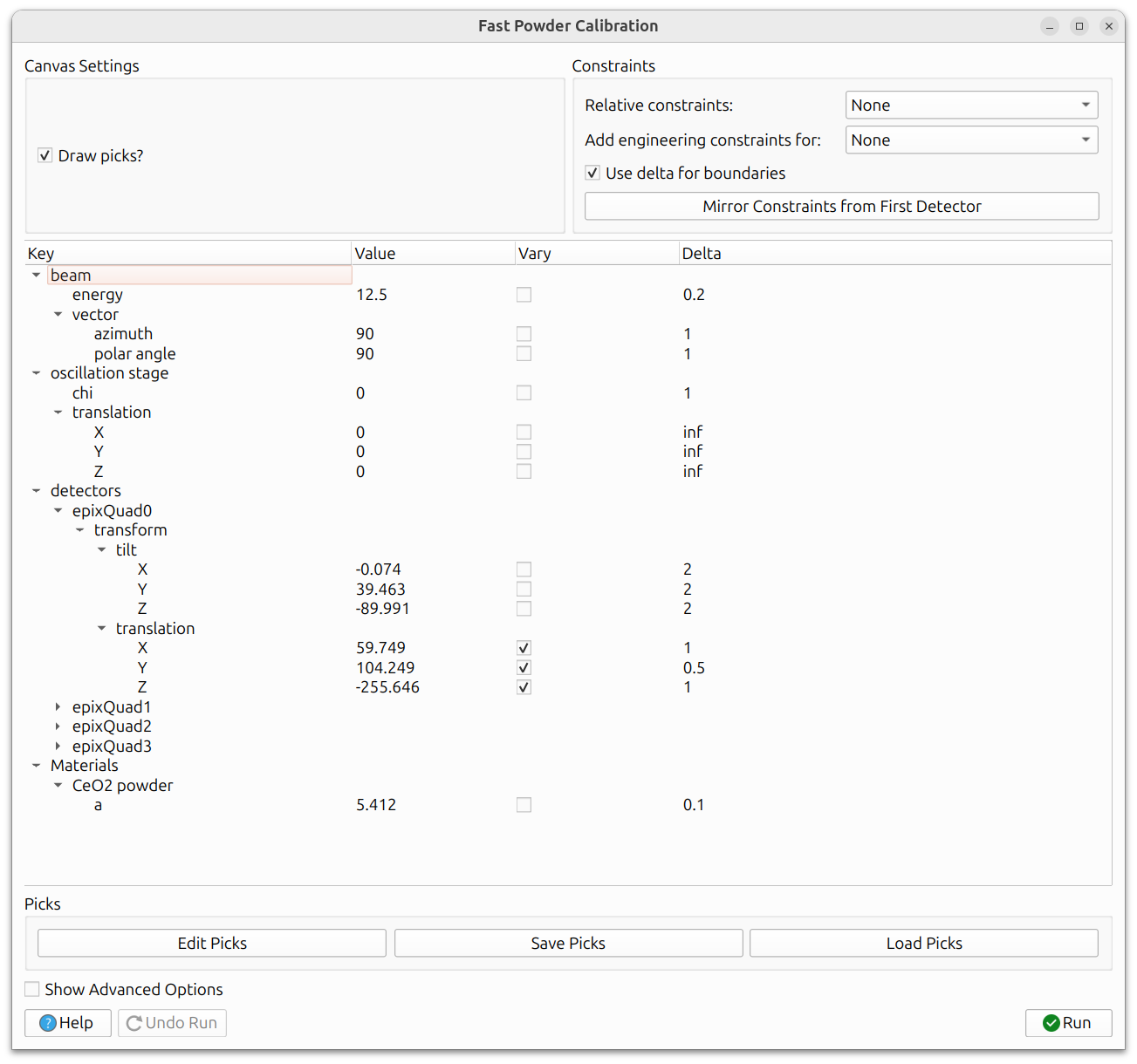
Use the "Vary" checkbox to select which parameters to refine. The same iterative strategy applies here as with other calibrations: start with a few parameters, run, then add more. See General Calibration Information for detailed guidance on calibration strategy, constraints, delta boundaries, and advanced options.
The residual being minimized is the distance between the auto-picked peak positions and the simulated powder line positions.
Running and Undoing
Click the Run button to execute the calibration. The refined parameters will be applied, and you should see the simulated lines shift to better match the data. If the result is not satisfactory, click Undo Run to revert to the previous state. A full undo stack is maintained, so you can undo multiple runs.
When you are satisfied with the calibration results, close the dialog to finish the workflow.